
What is a frequency converter and what is it required for?
The introduction of frequency converters into industrial plants began in the early 1970s. Until then, it was only possible to operate electric motors directly on the grid and thus at defined speeds. If an electric motor, e.g. an asynchronous machine, is operated directly on the grid (50Hz), a fixed speed is set, known as the nominal speed, based on the grid frequency and the pole number of the motor. In the past, where different speeds were required due to the application, mechanical gears were used. Some readers may remember what was known as the “delta changeover”. This was used to limit the power of the motor at the moment it is switched on in the case of directly operated motors.
What do variable motor speeds have in common with energy savings?
The option of continuously adjusting the motor speed offers an opportunity to save energy in many applications with different loads. For example, fans or pumps are only rarely operated at nominal power or speed. If a lower pumping capacity or conveyor volume is required, the frequency converter can easily reduce the power. Another advantage of using frequency converters (compared to motors that operate statically on the grid) is the improved process control of drives or machines thanks to the variable speed, which can often increase precision, quality and throughput.
Anyone who thinks that frequency converters can only be found in an industrial environment is mistaken. They have also long been used in the private sector. For example, frequency-converter-controlled motors with controlled speed can be found in kitchen machines, clothes dryers or heating or circulating pumps. Frequency converters are also found in electric vehicles in a modified form; however, they are operated with battery power, i.e. direct voltage.
How does a frequency converter work?
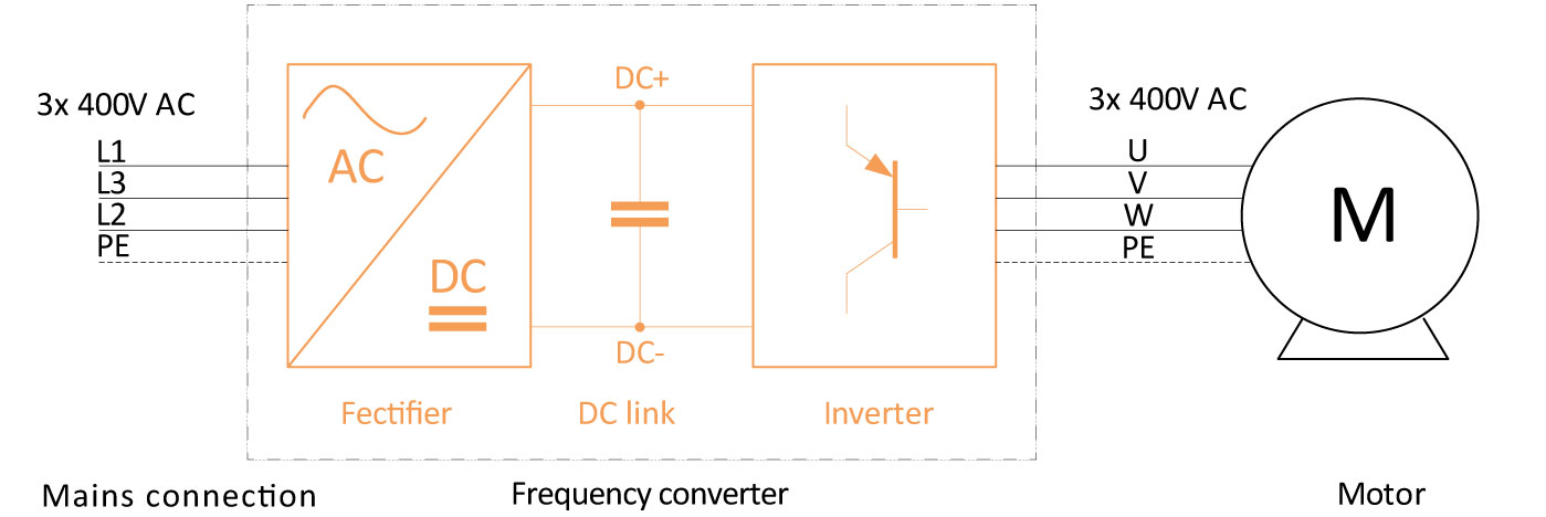
A frequency converter (AKA variable frequency drive) is a device that generates another alternating current with a different frequency and/or amplitude from an alternating current. A frequency converter typically consists of three components:
- Rectifier → the input mains alternating voltage is converted into a direct voltage here. This is normally done with a semiconductor bridge rectifier.
- DC intermediate circuit → intermediate voltage (= direct voltage) from which the inverter is supplied. Components for signal filtering are often found in the intermediate circuit to, for example, comply with the normative limit values regarding electromagnetic compatibility.The typical intermediate circuit voltage for a three-phase connection is 565 V DC.
- Inverter → semiconductor switching elements, e.g. transistors, that are controlled by pulse-width modulation (PWM for short). Any current sequences can be mimicked by “skilful” control of the switching elements. The current at the frequency converter output supplies the electric motor and is an alternating current with a sinusoidal course and variable frequency.
What is pulse-width modulation?
Pulse-width modulation is a square-wave signal with a constant pulse duration, which oscillates between two constant voltage values (in our example, half the intermediate circuit voltage +/- 1/2*UZ). The duty cycle, i.e. the ratio of pulse width to break width, varies here. Depending on the variant, different signal forms can be imitated. If an effective value is formed from the “hacked” PWM signal, the signal form corresponds to a sinusoidal alternating voltage.
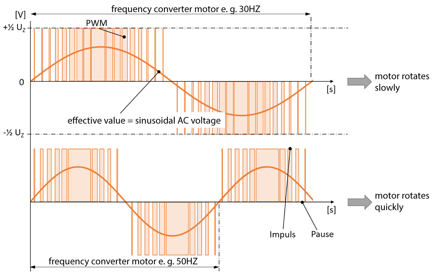
The major advantage of PW modulation is the high efficiency, as the transistors can be operated in efficient switching mode. In contrast, operation in amplifier mode would be more technically complex and generate more losses, as too much power would be converted into heat.
Incidentally, inverters for PV systems, digital Hi-Fi amplifiers and speed controllers for brushless motors in RC model construction also work according to this principle.
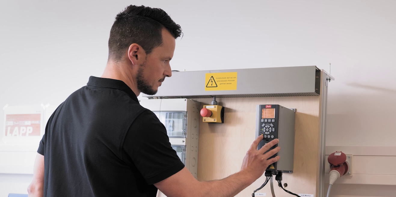
What is special about our ÖLFLEX® VFD or SERVO cables
Alongside the described benefits of variable speed control and the high saving potential, the PW modulation explained above unfortunately also has undesirable side effects. As a result, high voltages are switched from plus to zero volts within a few nano seconds. In the switching process itself, transients are formed, which can spread through electromagnetic couplings within the system, but also within our ÖLFLEX® motor cables. These high-frequency interference currents can stray through the factory earthing system and have a negative impact on the transmission quality of, for example, parallel data cables. However, these problems can be avoided through special cable designs, special insulation materials, and installation by trained specialist personnel.
Outlook – which new developments are in the pipeline?
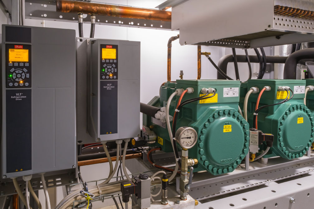
In today’s day-to-day industrial environment, almost all motors are controlled using frequency converters. The number of these drive trains will increase sharply, particularly in the small power classes. One reason for this is the low price, which makes gears for multi-axial drives unprofitable. In addition, logistics and handling applications increase the need for small drives and frequency converters.
In terms of technology, there are new developments in the field of semiconductors. For example, the innovative silicon carbide transistors (SiC) can be used to significantly reduce energy losses within frequency converters. This means that devices in the same power classes can be constructed much smaller in the future, as less heat loss needs to be discharged.